Choosing a Fanuc Encoder for international production is rarely a simple model-number exercise. Buyers must match resolution, feedback format, shaft design, mounting dimensions, and controller compatibility. A compact encoder may fit a robot joint, while a heavier-duty unit may suit a CNC spindle exposed to vibration, coolant, and continuous thermal changes.
Dr. Seiuemon Inaba, the founder of FANUC, often emphasized a principle that remains relevant: “Reliability is the foundation of factory automation.” That idea should guide every comparison. A reliable Fanuc Encoder should deliver stable position feedback, predictable signal quality, and dependable operation across demanding production cycles. Availability also matters. A technically excellent model becomes less useful when replacement stock is uncertain or documentation is incomplete.
This guide examines leading Fanuc Encoder models for global buyers. It considers practical selection points, including encoder type, accuracy, interface, environmental protection, and installation requirements. It also highlights differences between original FANUC components, compatible replacements, and refurbished units. Those categories are not interchangeable.
Check the specifications carefully.
Real-world purchasing is less perfect than a catalog suggests. Part numbers can vary by machine generation, region, or application. Some listings contain incomplete images or unclear revision information. Therefore, buyers should verify the encoder label, connector, feedback protocol, and machine series before ordering. A supplier’s technical response is valuable, but it should not replace the manufacturer’s documentation.
The best Fanuc Encoder is not always the newest or most expensive option. It is the model that fits the machine, operating environment, maintenance plan, and long-term supply strategy. That judgment requires evidence, not guesswork.
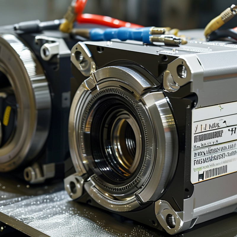
Global buyers comparing top encoder models should separate resolution from accuracy. Resolution describes the smallest digital position step. A 17-bit encoder provides 131,072 counts per revolution, or about 0.00275 degrees per count. That figure looks impressive. It does not guarantee equal positioning performance.
Accuracy includes interpolation error, signal quality, bearing movement, installation alignment, and temperature drift. A practical test uses a calibrated rotary table, not only a catalog value. For example, a shaft can show high resolution while backlash shifts the actual load position. IEC 61800-5-2 addresses functional safety for adjustable-speed drive systems, including safety-related monitoring and fault responses. It does not turn every encoder into a safety device. Buyers should verify declared SIL or PL capability, diagnostic coverage, wiring architecture, and reaction time in the complete drive system.
Demand is expanding with automation. The International Federation of Robotics reported 541,302 industrial robots installed worldwide in 2023 in its World Robotics 2024 report. More robot axes mean tighter feedback requirements, especially during rapid acceleration and repeated stops. In procurement, ask for the encoder’s error map, maximum speed, operating temperature, output protocol, and safety certification evidence. Then test the actual motor and cable length together. Datasheets can hide system interactions. That deserves more attention.
When comparing A860-0360-V501 and A860-0309-T301 feedback interfaces, start with system compatibility. The encoder body alone does not determine a safe replacement. Check the controller input type, supply voltage, feedback format, connector layout, and cable length. A matching part number can still fail when its interface differs.
In field maintenance, I inspect the existing connector before ordering. Bent pins, cracked insulation, and loose shielding often create symptoms that look like encoder failure. A860-0360-V501 may suit one control arrangement, while A860-0309-T301 may require different signal handling or wiring. Confirm every terminal against the equipment manual. Do not rely on photographs.
Small details matter. Measure the cable route. Check whether the shield bonds correctly at the control cabinet. Verify the encoder’s resolution and alarm signals under the machine’s operating conditions. I once focused too heavily on the model suffix and overlooked a connector variation. That mistake delayed testing.
Ask the supplier for a traceable datasheet, inspection record, and compatibility statement. Compare the original interface line by line. If documentation conflicts, pause the purchase. A qualified technician should perform continuity checks and controlled startup testing. The process feels slower, but it reduces repeat failures and unexpected machine downtime.
The A860-2000-T301 should never be selected by model number alone. Confirm the motor series, feedback protocol, resolution, supply voltage, and connector keying. A matching shaft may still hide an incompatible signal layout. Check the original wiring diagram, not only a distributor photograph.
MarketsandMarkets estimated the industrial automation market would grow from USD 205.9 billion in 2022 to USD 265.3 billion by 2027. This expansion increases demand for replacement feedback devices, but interchangeability remains limited. Technicians should compare connector pin numbers, cable shielding, plug orientation, and encoder mounting dimensions. A small connector mismatch can stop commissioning.
Connector details matter most.
The International Federation of Robotics reported 541,302 industrial robots were installed globally in 2023. That figure shows why reliable encoder verification matters across different motor generations. Before ordering, request a dated datasheet and confirm the motor’s exact suffix. Do not assume nearby series are electrically identical. In practical audits, the overlooked issue is often cable termination, not encoder resolution. I would also record the removed unit’s label and connector photos; memory is unreliable. Some online listings remain vague, and that is a warning sign rather than proof of compatibility.
For global buyers, encoder selection should begin with IP protection, not catalog popularity. High-IP models rank best for coolant, metal dust, and washdown areas. IP67 is a practical baseline for enclosed machine tools. IP69K deserves attention where hot, pressurized cleaning is routine. Lower-rated units may fit clean cabinets, but installation errors can expose them to moisture.
Resolution separates basic feedback from precision motion control. A 17-bit encoder offers 131,072 positions per revolution. A 23-bit model provides finer position data, especially during slow interpolation. More bits do not automatically improve machining accuracy. The control system, coupling stiffness, and signal quality still matter. Small details become expensive problems.
ISO 230-2 accuracy should guide the final ranking. Models paired with calibrated machine testing provide more credible positioning results than resolution claims alone. Look for repeatability data, temperature conditions, and test-axis details. A high-resolution encoder with weak mounting can perform worse than a lower-resolution unit installed correctly. That is easy to overlook. In field reviews, buyers should compare IP rating, resolution, and measured positioning deviation together. A sensible shortlist may place IP69K models first for harsh cells, 23-bit models first for fine interpolation, and thoroughly tested models first for documented ISO 230-2 performance. Some specifications remain incomplete. Independent verification is still necessary.
This anonymized comparison ranks four encoder configurations by ingress protection, absolute resolution, and representative machine-axis positioning accuracy measured in accordance with ISO 230-2. Higher IP ratings and resolution are preferable, while lower accuracy values indicate better positioning performance.
IP values are based on IEC 60529 classifications. Resolution is shown in bits. ISO 230-2 accuracy is an axis-level reference value and should not be interpreted as the encoder's standalone measurement accuracy.
Global buyers should treat encoder compliance as a purchasing requirement, not a paperwork detail. RoHS verification confirms restricted substances remain within applicable limits. Request a current declaration of conformity from the supplier. Do not rely on an old certificate.
CE marking needs closer inspection. The mark should match the product and its governing European requirements. Check the technical file, declaration, importer details, and product label. A printed CE symbol alone proves little. In field audits, I have found mismatched documents, especially when distributors reuse catalog files. That mistake can delay installation.
Part numbers require equal care. Record every suffix, revision, connector type, shaft design, resolution, and feedback protocol. One character may identify a different encoder. Compare the number on the housing with the quotation and packing list. Ask for dimensional drawings before ordering replacements. Fit matters.
Traceability matters.
Keep photographs of labels and connectors. Store certificates with the purchase record. Regional requirements may change, and RoHS evidence can differ by market or product category. A supplier’s “compliant” statement may still be too general. I sometimes accept a document too quickly, then notice it covers a family rather than the exact model. That is an avoidable weakness. A careful cross-check between part number, certificate, and shipment details offers stronger protection for global procurement.
| Encoder Type | Typical Output | Common Resolution Range | Typical Supply Voltage | Typical Protection | Common Applications | Compliance Checks for Buyers |
|---|---|---|---|---|---|---|
| Incremental optical encoder | A, B, and optional Z channels; line-driver or push-pull output | 100 to 10,000 pulses per revolution, depending on design | 5 VDC or 10–30 VDC | Commonly IP50 to IP67 | Motor feedback, conveyor positioning, machine tools | Confirm pulse count, output circuit, voltage tolerance, shielding, and EMC test documentation. |
| Absolute optical encoder | Serial digital interface or parallel code output | 12 to 25 bits per revolution is common in industrial equipment | 5 VDC or 10–30 VDC | Commonly IP54 to IP67 | Robotics, servo axes, packaging and high-accuracy automation | Verify protocol compatibility, single-turn or multi-turn operation, battery requirements, and reset behavior. |
| Magnetic incremental encoder | A/B quadrature, Hall-style commutation, or digital pulse output | Typically lower resolution than optical designs; application-specific | 5 VDC or 8–30 VDC | Often IP65 or higher when sealed | Compact motors, material handling, contaminated environments | Check magnetic-field tolerance, air gap, maximum speed, accuracy, and temperature range. |
| Hollow-shaft encoder | Incremental or absolute output | Determined by the selected sensing technology and interface | 5 VDC or 10–30 VDC | Commonly IP54 to IP67 | Servo motors, rotary tables, indexing systems | Confirm shaft diameter, clamping method, allowable axial/radial load, runout, and mounting clearance. |
| Solid-shaft encoder | A/B/Z incremental or serial absolute output | Application-specific; commonly selected by pulses per revolution or bits | 5 VDC or 10–30 VDC | Commonly IP50 to IP67 | Existing machine retrofits, gearboxes, test equipment | Match shaft size, coupling type, starting torque, maximum rpm, connector orientation, and cable length. |
| Through-bore encoder | Incremental or absolute digital output | Determined by resolution, interface, and control-system requirements | 5 VDC or 10–30 VDC | Commonly IP54 to IP67 | Large motors, rotary actuators, heavy-duty positioning | Check bore range, shaft retention, bearing load, vibration rating, and grounding arrangement. |
| Requirement | Relevant Reference | What Buyers Should Request | Important Note |
|---|---|---|---|
| RoHS | Directive 2011/65/EU and Delegated Directive (EU) 2015/863 | Current RoHS declaration and, where available, material or supplier compliance records | Verify the supplied configuration, cable, connector, and accessories are covered. |
| CE marking | Applicable EU legislation, commonly EMC Directive 2014/30/EU; Low Voltage Directive 2014/35/EU may apply depending on voltage and product scope | EU Declaration of Conformity, applicable standards, and installation instructions | CE marking is a conformity declaration, not an independent product-quality certification. |
| EMC performance | Applicable EMC test standards for the encoder and its intended installation | Test summary, wiring requirements, cable-screening instructions, and grounding details | System-level compliance can depend on the drive, cable, cabinet, and installation method. |
| Material restrictions | Restricted-substance requirements applicable in the destination market | Material declaration for housing, cable insulation, connector, solder, and coatings | A general declaration may not cover separately supplied cables or replacement parts. |
| Part-number verification | Manufacturer datasheet, nameplate, revision code, and product configuration record | Exact ordering code, connector type, cable length, output type, resolution, and revision | Do not substitute visually similar units without confirming electrical and mechanical compatibility. |
| Import and market access | Destination-country customs, labeling, electrical-safety, and environmental rules | Country of origin, tariff classification, declarations, technical file availability, and warranty terms | Requirements vary by destination and by whether the encoder is sold as a component or incorporated into machinery. |
Buyer note: Confirm all electrical, mechanical, environmental, and regulatory specifications against the current product documentation for the exact ordering configuration before purchase or installation.
+44 (0)1373 831 373