Global power distribution is becoming more demanding, not merely larger. The International Energy Agency’s Electricity 2024 report forecasts global electricity demand growth of about 3.4% annually through 2026. That growth places pressure on medium-voltage networks, especially in urban substations, renewable-energy projects, and industrial facilities.
Rmu Switchgear offers a compact way to manage these pressures. It combines switching, protection, and isolation inside a factory-tested enclosure. A typical unit can fit beside a transformer in a narrow concrete kiosk, reducing installation space and maintenance exposure. Its modular design also supports phased network expansion. Practical value matters.
Frédéric Godemel, Schneider Electric’s Executive Vice President for Power Systems and Services, has stated, “The energy transition is an electrification transition.” His observation explains why dependable medium-voltage equipment is becoming central to global infrastructure planning. The IEA’s Grid Investment report also highlights the need for faster investment in modern, flexible electricity networks.
However, Rmu Switchgear is not automatically the best choice. Engineers must verify fault ratings, climate conditions, remote-control requirements, service access, and local standards. IEC 62271-200 provides an important reference for metal-enclosed medium-voltage switchgear. Environmental performance also deserves closer attention, particularly where traditional SF6 insulation is used.
The better question is not whether Rmu Switchgear looks compact. It is whether the selected design remains safe, maintainable, and adaptable across decades of changing power demand. That answer depends on engineering evidence, supplier experience, and honest lifecycle evaluation.
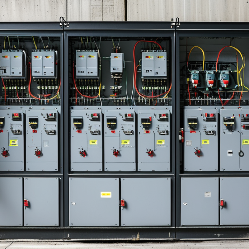
RMU Switchgear Defined: IEC 62271-200 Medium-Voltage Distribution
RMU switchgear is compact metal-enclosed equipment for medium-voltage networks. It controls, protects, and isolates distribution circuits in a small footprint. IEC 62271-200 applies to AC metal-enclosed switchgear above 1 kV and up to 52 kV. Common RMU assemblies include load-break switches, circuit breakers, earthing switches, and fuses. These functions support ring networks, where power can arrive from different directions. That improves supply continuity. Space remains limited.
In practical installations, technicians use visible position indicators and interlocking systems during switching operations. A sealed enclosure helps protect internal components from dust, moisture, and accidental contact. However, sealed does not mean maintenance-free. Cable terminations, pressure indicators, and operating mechanisms still need inspection. Internal arc classification also matters, especially in substations near buildings or public areas. Local installation conditions can change the correct specification.
For global power distribution, engineers should verify voltage, short-circuit withstand, insulation level, and environmental requirements. IEC 62271-200 compliance provides a reliable technical reference, but it does not replace site engineering. Cable interfaces must match local practices and available accessories. Protection settings should reflect transformer capacity and network fault levels. Field experience often reveals small problems early, such as unclear labels or restricted operating space. These details seem minor. They are not. Even a well-designed RMU can perform poorly when installation records, training, or maintenance access are overlooked.
Why Choose RMU Switchgear for Global Power Distribution?
Voltage Classes from 12 to 36 kV for Global Utility Networks
RMU switchgear supports compact, dependable distribution across urban networks, industrial sites, and renewable energy projects. Its voltage range, from 12 to 36 kV, suits different utility conditions and planning standards. At 12 kV, it commonly serves local feeders and commercial districts. Higher classes, such as 24 and 36 kV, support longer routes and larger loads.
Voltage selection requires more than matching the nominal system value. Engineers must review insulation levels, fault current, altitude, humidity, and future expansion. A 24 kV network may need different clearances than a 12 kV installation. Indoor substations also demand careful attention to ventilation, cable bending space, and operator access. Small details matter.
Field planning often reveals practical advantages. RMU units can reduce substation footprints and simplify feeder switching during maintenance. Sealed compartments help protect primary components from dust and moisture. However, no enclosure solves every problem. Poor cable termination, weak grounding, or unclear operating procedures can still create serious risks. That part is easy to underestimate.
The 12–36 kV range also supports staged grid development. Utilities can standardize equipment while adapting protection settings and network layouts. Testing should follow applicable local standards and verified manufacturer data. Documentation must remain clear. This is where reliable engineering practice matters most.
IEC-aligned medium-voltage switchgear classes from 12 to 36 kV support a wide range of utility distribution networks. The exact nominal network voltage varies by country and utility, while the equipment rating provides the required insulation and switching capability.
Typical application: 12 kV equipment commonly serves 11 kV networks, 17.5 kV equipment supports intermediate-voltage systems, 24 kV equipment is widely used for 20–22 kV networks, and 36 kV equipment is suitable for 33 kV distribution systems.
Why Choose RMU Switchgear for Global Power Distribution?
Compact Design with 3–5 Functional Ways in Urban Substations
In dense cities, every square meter has a cost. RMU switchgear places switching, protection, and cable connections inside one compact metal enclosure. Three to five functional ways can serve incoming feeders, outgoing feeders, transformers, or bus-section duties. This arrangement reduces substation footprint without removing essential operating functions. Field engineers often value the clear layout during maintenance. A smaller room also simplifies civil construction and cable routing.
RMU units support ring-network operation, which helps isolate a faulty section while keeping other feeders energized. This matters in hospitals, apartment towers, rail stations, and commercial districts. Sealed compartments can limit exposure to dust, moisture, and accidental contact. However, compact equipment is not automatically easier to maintain. Poor labeling, restricted access, or incorrect cable termination can create serious delays. Engineers should verify ratings, interlocking logic, earthing arrangements, and local grid requirements before installation. Real projects sometimes reveal that a “standard” configuration needs adjustment.
Tips: Leave enough working clearance around the enclosure. Confirm cable bending space early. Test mechanical and electrical interlocks before energization. Record inspection results clearly. Do not treat a compact footprint as permission to reduce safety checks. Regular inspection remains necessary, even when the switchgear appears clean and undamaged.
Why Choose RMU Switchgear for Global Power Distribution?
Medium-voltage networks demand more than compact equipment. They need predictable fault performance. RMU switchgear rated for 16–25 kA can withstand severe short-circuit forces when correctly specified. IEC 62271-200:2021 defines internal-arc testing, access classifications, and enclosure performance requirements. These tests examine hot gases, pressure, doors, covers, and nearby indicators. The goal is practical: protect operators standing near the panel.
CIGRE Technical Brochure 537 explains how internal-arc classification supports safer application of metal-enclosed switchgear. An AFLR classification covers the front, lateral, and rear accessibility required by the installation design. At 25 kA for one second, the fault carries 25,000 amperes through the enclosure. That energy can deform metal rapidly. Strong earthing, pressure-relief paths, interlocked access, and shielded cable compartments therefore matter. Small details matter.
Field experience also shows a difficult truth. A certified assembly does not remove every hazard. Incorrect cable termination, aging insulation, or poor maintenance can defeat otherwise sound protection. IEC 62271-1 provides general service and testing principles, while local rules determine installation practice. Operators should verify the prospective fault current, clearing time, enclosure class, and protection coordination before selecting equipment. A lower rating may be unsafe. An oversized rating may increase cost without improving the real risk profile. Engineering judgment remains essential.
| Safety or Performance Dimension | Typical Data or Requirement | Safety Benefit in 16–25 kA Networks | Verification Point |
|---|---|---|---|
| Rated voltage | Commonly 12 kV, 17.5 kV, 24 kV or 36 kV | Provides insulation and switching capability suitable for medium-voltage distribution systems. | Confirm that the rated voltage is equal to or higher than the highest system operating voltage. |
| Short-circuit breaking current | 16 kA, 20 kA or 25 kA rms symmetrical, typically for 1 second | Allows the circuit breaker or fuse-switch combination to interrupt prospective fault current without unsafe loss of function. | Match the equipment rating with the calculated prospective short-circuit current at the installation point. |
| Short-time withstand current | 16–25 kA for 1 second is a common medium-voltage design range | Withstands thermal and electrodynamic forces while upstream protection clears a fault. | Check both the rms value and the specified duration; a higher peak withstand rating may also be required. |
| Peak withstand current | Often approximately 2.5 times the rated short-time withstand current at 50 Hz | Limits mechanical damage caused by the first high-current asymmetrical peak of a short circuit. | Use the exact manufacturer declaration and applicable standard value rather than estimating for final design. |
| Switching technology | Vacuum circuit breaker or load-break switch with current-limiting fuses | Vacuum interruption reduces arc duration in the interrupter; properly coordinated fuses can limit fault energy. | Verify interrupting capacity, making capacity, duty-cycle rating and protection coordination. |
| Earthing switch | Fault-making earthing switch where specified; short-time withstand aligned with the assembly rating | Provides a controlled discharge path and supports safe maintenance after isolation. | Confirm making capacity, interlocking arrangement and the earthing switch position indication. |
| Mechanical interlocking | Prevents unsafe sequences such as closing the earthing switch onto an energized circuit | Reduces operator error during switching, isolation and maintenance procedures. | Test all permitted and prohibited operating sequences during commissioning. |
| Key or electrical interlocking | Optional trapped-key, solenoid or control-circuit interlocking | Adds procedural control between cable compartments, bus sections, circuit breakers and earthing points. | Ensure the interlock logic reflects the site operating procedure and emergency bypass policy. |
| Internal arc classification | IAC AFL, AFLR or another declared classification under IEC 62271-200 | Helps protect personnel from hot gases, pressure and ejected parts during an internal arc event. | Check the tested current, test duration, accessibility sides and installation conditions; IAC is not automatic for every RMU. |
| Arc-fault pressure relief | Pressure-relief flaps, ducts or a defined exhaust path, depending on enclosure design | Directs hot gases away from accessible areas and reduces enclosure overpressure during an internal fault. | Maintain the required clearance and never obstruct pressure-relief routes. |
| Sealed primary enclosure | Sealed-for-life gas or solid-insulated primary compartment, depending on design | Reduces exposure to dust, humidity and accidental contact with energized primary parts. | Check enclosure integrity, gas-pressure indication where applicable and end-of-life handling requirements. |
| Loss-of-service continuity | Larger RMUs may offer LSC2A or LSC2B classifications, depending on construction | Defines how far adjacent compartments can remain energized during access or maintenance activities. | Confirm the declared LSC classification and the permitted access conditions for each compartment. |
| Partition classification | PM or PI classification, depending on whether partitions are metallic or insulating | Indicates the material and continuity of partitions between functional units and accessible areas. | Review the type-test declaration and ensure the classification meets the system safety philosophy. |
| Cable testing and access | Dedicated cable compartment with screening, shutters or defined test points | Supports voltage testing, phasing and cable maintenance while limiting access to adjacent live parts. | Verify the approved test procedure, voltage-detection method and isolation requirements. |
| Voltage presence indication | Capacitive voltage detection system, commonly designed according to IEC 62271-213 | Provides a visible indication that a circuit may be energized before earthing or cable work. | Use an approved proving unit and never treat indication alone as proof of deadness. |
| Protection and control | Overcurrent, earth-fault, transformer protection and optional remote-control functions | Detects abnormal conditions and reduces fault-clearing time, limiting thermal and mechanical stress. | Coordinate pickup values, time delays, CT performance and breaker operating time with the network study. |
| Environmental protection | Typical indoor enclosures: IP2X or higher for accessible external surfaces; higher IP ratings may apply | Limits accidental contact and protects internal components from solid objects and moisture according to the declared rating. | Confirm the required IP level, ambient temperature, altitude, condensation and pollution conditions. |
| Standards and type testing | IEC 62271-200 for AC metal-enclosed switchgear; IEC 62271-100 for AC circuit breakers; IEC 62271-102 for disconnectors and earthing switches | Provides a recognized basis for dielectric, temperature-rise, short-circuit, mechanical and internal-arc performance. | Request current type-test reports and ensure the tested configuration matches the proposed RMU arrangement. |
| Installation and maintenance safety | Clear operating instructions, mimic diagram, padlocking points, safe access zones and documented maintenance intervals | Converts equipment capability into consistent safe operation throughout the asset life. | Follow local electrical-safety rules, lockout/tagout procedures and the approved switching schedule. |
Reliable power distribution often depends on details that are easy to overlook. Frequency is one of them. RMU switchgear designed for 50/60 Hz systems can support projects across regions with different grid conventions. However, frequency compatibility is not enough by itself. Engineers should verify rated voltage, insulation level, short-circuit capacity, protection settings, and enclosure requirements. A well-selected RMU can operate in compact substations, industrial facilities, and commercial buildings where space is limited. Field experience shows that clear documentation prevents many commissioning delays.
Tips: Confirm the local grid frequency before ordering. Check whether protection relays, meters, transformers, and auxiliary circuits match 50 Hz or 60 Hz operation. Review terminal markings carefully. Small differences matter. Also request routine test records, wiring diagrams, and installation instructions. These documents help technicians identify mistakes before energization.
A 50/60 Hz compatible RMU should be assessed as part of the complete distribution system. Cable ratings, earthing design, load profiles, and switching sequences must work together. In practice, some projects focus heavily on frequency and overlook heat, humidity, dust, or altitude. That can weaken long-term reliability. It is worth reviewing local operating conditions with qualified engineers and arranging site acceptance tests. No design is perfect on paper. Real equipment behavior deserves attention.
+44 (0)1373 831 373